doi: 10.56294/saludcyt2024.900
ORIGINAL
Prototype of innovative device for chest compression at the Universidad Private del Valle in Cochabam-ba, Bolivia
Prototipo de dispositivo innovador para compresión torácica en la Universidad Privada del Valle en Cochabam-ba, Bolivia
Marco Fabian Borda Wiegert1
![]() *, Mauricio Marcelo Peredo Claros1
*, Mauricio Marcelo Peredo Claros1
![]() *, Eynar Calle Viles1
*, Eynar Calle Viles1
![]() *, Rommer Alex Ortega Martinez1
*, Rommer Alex Ortega Martinez1
![]() *
*
1Universidad Privada del Valle. Cercado/Cochabamba, Bolivia.
Cite as: Borda Wiegert MF, Peredo Claros MM, Calle Viles E, Ortega Martinez RA. Prototype of innovative device for chest compression at the Universidad Private del Valle in Cochabamba, Bolivia. Salud, Ciencia y Tecnología. 2024; 4:.900. https://doi.org/10.56294/saludcyt2024.900
Submitted: 17-02-2024 Revised: 22-05-2024 Accepted: 28-08-2024 Published: 29-08-2024
Editor:
Dr.
William Castillo-González ![]()
Corresponding Author: Marco Fabian Borda Wiegert *
ABSTRACT
This article presents the development of a portable automatic chest compressor device using a rod-crank-piston mechanism. The main focus is on assessing the feasibility of manufacturing the device in Bolivia, primarily utilizing 3D printing technology and locally accessible components to create an economical device. The methodology involved reviewing appropriate techniques of Cardiopulmonary Resuscitation (CPR), analyzing the proposed mechanism, and researching chest compression devices available in the market for insights. Using this information as a foundation, a device inspired by the Weil Mini model was designed but implementing a rod-crank-piston mechanism for compressions. The construction of the prototype progressed through different phases, culminating in a portable device with manual control and the ability to store treatment data in a wirelessly connected application, allowing for equipment maintenance by service personnel. The conducted tests yielded satisfactory results, demonstrating that the device correctly compressed a calibrated CPR manikin, meeting all the requirements established by the American Heart Association (AHA) standards. Additionally, the development of software, implemented safety systems, and the creation of the web application for maintenance and data logging represent distinctive features of the prototype.
Keywords: Cardiopulmonary Resuscitation; Heart Arrest; Heart Massage; Prototype.
RESUMEN
Este artículo presenta el desarrollo de un dispositivo automático portátil de compresión torácica que utiliza un mecanismo de biela-manivela-pistón. El enfoque principal es evaluar la factibilidad de fabricar el dispositivo en Bolivia, principalmente utilizando tecnología de impresión 3D y componentes accesibles localmente para crear un dispositivo económico. La metodología consistió en revisar las técnicas apropiadas de reanimación cardiopulmonar (RCP), analizar el mecanismo propuesto e investigar los dispositivos de compresión torácica disponibles en el mercado. Con esta información como base, se diseñó un dispositivo inspirado en el modelo Weil Mini, pero implementando un mecanismo de biela, manivela y pistón para las compresiones. La construcción del prototipo avanzó a través de diferentes fases, culminando en un dispositivo portátil con control manual y capacidad para almacenar los datos del tratamiento en una aplicación conectada de forma inalámbrica, permitiendo el mantenimiento del equipo por parte del personal de servicio. Las pruebas realizadas arrojaron resultados satisfactorios, demostrando que el dispositivo comprimía correctamente un maniquí de RCP calibrado, cumpliendo todos los requisitos establecidos por los estándares de la American Heart Associ-ation (AHA). Además, el desarrollo del software, los sistemas de seguridad implementados y la creación de la aplicación web para el mantenimiento y registro de datos representan características distintivas del prototipo.
Palabras clave: Reanimación Cardiopulmonar; Parada Cardiaca; Masaje Cardiaco; Prototipo.
INTRODUCTION
Cardiopulmonary Resuscitation (CPR) consists of maneuvers designed to reverse cardiorespiratory arrest (CA) and restore spontaneous breathing and circulation, thereby preventing death from irreversible injury to vital organs, particularly the brain.(1) This procedure involves applying uninterrupted rhythmic chest compressions to the patient at least 5 centimeters, ensuring complete relaxation between compressions, and maintaining a frequency of 100 to 120 compressions per minute.(2,3) It is crucial to prevent hyperventilation.(4) Survival rates from cardiac arrest (CA) could triple if basic CPR were performed by bystanders or first responders.(5)
However, the effective implementation of CPR requires a specific training, which covers everything from the frequency and depth of compressions to the proper positioning of the patient. Although emergency personnel, such as paramedics and intensive care staff, are trained to perform these techniques, they face significant challenges when applying CPR. It must be performed universally for 2 minutes in a sequence of 30 compressions and 2 ventilations, followed by a pulse recovery check lasting less than 10 seconds.(6) Due to this demanding sequence, physical exhaustion is a major issue, as they often become fatigued before 60 seconds but do not realize it until the 2-minute mark.(7) This exhaustion limits the ability to maintain CPR with effective frequency and depth for prolonged periods, decreasing the patient’s chances of survival.(8)
Additionally, moving the patient during CPR presents a significant challenge, as it disrupts the procedure and can negatively impact the immediate care required. To address these issues, automatic chest compression devices have been developed, such as the Lucas 3.1, which performs compressions through a piston mechanism, and the AutoPulse device, which uses a load-distributing band. These devices free healthcare professionals from the task of performing manual compressions, allowing them to focus on other critical actions.(9) However, these devices come with a high cost: the Lucas 3.1 and the AutoPulse costs approximately 20 000 USD.
However, in regions like Cochabamba, Bolivia, these devices are not available due to their unaffordable costs. In this situation, there is a need to develop accessible and effective alternatives.
This article addresses the design and development of a chest compression device based on an innovative rod-crank-piston system. This approach, widely used in mechanical engineering, is presented as a viable solution to provide the necessary compressions in a low-cost and easy-to-manufacture device.
METHOD
For the development of the chest compression device, thorough research was conducted on the appropriate CPR techniques and current regulations in Bolivia. This ensured that the prototype implementation complied with relevant standards, in addition to being observed by local instructors authorized by the AHA.
A detailed analysis of CPR equipment available in the international market was carried out to understand their operation, identify advantages and disadvantages, and design a new model that integrated the best features of each while addressing and improving observed deficiencies. This approach ensured that the equipment met necessary requirements and ensured patient safety.
With the collected information, the model to be built was defined, and a block diagram was developed to guide the construction of the device clearly and concisely, establishing its operation and capabilities.
The implementation of the device was divided into three progressive phases:
First Phase
· Mechanism and structure: a compression system with optimal dimensions was designed to ensure correct depth and frequency of CPR.
· Hardware: essential circuitry and a compression force measurement module were integrated.
· Physical assembly: all mechanical, structural, and hardware components were consolidated.
· Software: basic code was developed to control the device through a computer interface.
· Graphical user Interface (GUI): A desktop application was created for equipment control.
· Testing: tests were conducted, and observations were recorded.
Second Phase
· Mechanism and structure: the compression system was enhanced to ensure it has the strength and depth to perform a real CPR.
· Hardware: improved circuitry was implemented on a PCB (Printed Circuit Board), and a control panel was added to make the equipment portable.
· Physical assembly: all mechanical, structural, and hardware components were consolidated.
· Software: the code was improved to allow control via the control panel and a wireless interface.
· Graphical User Interface (GUI): the desktop application was enhanced to enable wireless communication with the equipment.
· Testing: tests were conducted, and observations were recorded.
Third Phase
· Mechanism and structure: the compression system was improved to ensure the necessary frequency, force, and depth for an effective CPR.
· Hardware: circuitry continued to be improved, and sensors were incorporated to monitor operational errors.
· Physical assembly: all mechanical, structural, and hardware components were consolidated.
· Software: error control systems were added to the code, and specific code was developed for maintenance via the wireless interface.
· Graphical User Interface (GUI): a web application was created with user levels and a special section for equipment maintenance.
· Testing: this phase focused on ensuring that the equipment meets all AHA regulatory requirements.
RESULTS
In Bolivia, the CPR technique is governed by the guidelines of the AHA regulations. Based on the 2020 AHA Update Guidelines,(10) successful CPR follows a series of fundamental steps to improve survival chances. These steps include early recognition of the need for CPR, application of chest compressions at a rate of 100 to 120 times per minute and a depth of at least 5 centimeters in adults and minimizing interruptions between compressions to maintain a constant blood flow to vital organs. These compressions should be accompanied by ventilations in a 30:2 sequence (30 compressions/2 ventilations) to avoid hyperventilation. The guidelines also recommend changing the person performing compressions every 2 minutes to reduce the effects of physical exhaustion.
Commercial Chest Compression Devices
Chest compression devices are classified into two fundamental categories based on their operating principle: piston devices and load-distributing band devices.(11) Next, three of the most representative models available in the international market are evaluated: Lucas, AutoPulse, and WeilMini. Each one presents distinctive features in terms of operating principle, portability, and efficacy, as well as specific advantages and limitations that must be considered when designing a new model of chest compression equipment.
The Lucas device (see figure 1a) utilizes a pneumatic piston for its operation and stands out for its capability of actively decompressing the patient’s chest.(12) However, its size and relative difficulty in placement compared to its competitors may be significant disadvantages in certain emergency scenarios.
On the other hand, the AutoPulse device (see figure 1b) uses a mechanically driven load-distributing band compressor, which provides automatic regulation to the patient and semicircular compressions around the chest, considered more effective. However, its limited compressions per minute capacity and its size and weight may affect its portability and practicality in emergency situations.(13)
Finally, the WeilMini device (see figure 1c) has a piston that depresses the sternum during the compression phase and a circumferential band that constricts the chest simultaneously with compressions.(14) It has a quick setup and requires external compressed air to operate.(15)
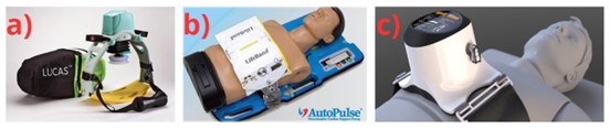
Source: a) GATIV, 2010, b) Czyż et al., 2018, c) Falk
Figure 1. a) LUCAS Chest Compressor, b) AutoPulse Chest Compressor, c) WeilMini Chest Compressor
Device Block Diagram
After analyzing the different options of chest compression devices available in the market, the portability and ease of placement of the WeilMini device were taken as an example. However, it was decided to replace the pneumatic mechanism with a rod-crank-piston system to address the dependency on external air compressor and improve manufacturing feasibility using Bolivian technology.
In addition to this decision, the incorporation of distinctive additional features was planned to enhance the functionality of the device and improve patient care. Among these features, a precise placement control system, an integrated digital recording through a database-based interface, and an equipment maintenance mode stand out. These unique features are not found in other commercial devices and ensure optimal device operation as well as effective medical care.
To materialize and guide this vision, a block diagram was developed, presented in figure 2. In this diagram, it is visualized how the microcontroller sends signals to the power circuit to activate the compression mechanism. At the same time, sensors and peripherals transmit information to the microcontroller, allowing for equipment monitoring and control to ensure its correct operation. Additionally, a control panel was incorporated to adjust the device’s operation mode according to user needs.
On the other hand, the microcontroller design facilitates its connection to a Graphical User Interface (GUI), where the information of each treatment is stored in a database. This allows medical professionals, such as paramedics or first aid personnel, to access this platform to associate treatments with patients and make adjustments as necessary. Likewise, biomedical personnel can use this interface to carry out device maintenance, ensuring its optimal operation over time.
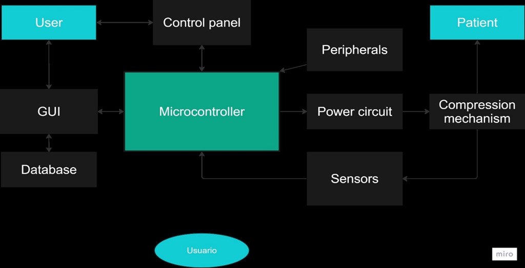
Figure 2. Device block diagram
Device Implementation
First Phase
Mechanism and Structure - First Phase
A rod-crank-piston system was chosen for the equipment, which involved its design and construction. This system converts continuous rotary motion into reciprocal linear motion and vice versa.(16) It consists of the articulation of the crank with the rod, whose foot is connected to the piston. The rotation of the crank triggers the movement of the rod and, consequently, the linear displacement of the piston (see figure 3).
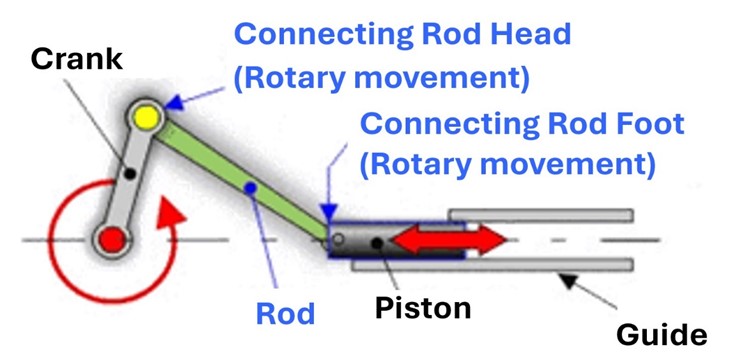
Source: Cejarosu
Figure 3. Rod-crank-piston System
The stroke of the piston, that is, the amplitude of its travel, is determined by the length of the crank, calculated using formula 1.
Stroke = 2∗ Crank Length (1)
Applying this formula to achieve a stroke of 5 cm, necessary for the compression of the device, it was determined that the optimal length for the crank was 2,5 cm. With this defined length, the 3D piece was designed with a special coupling for 5x10x4 mm bearings. To define the length of the connecting rod, initially, the CHW-GW4058-555 ABHL gear motor was selected to drive the mechanism. The connecting rod was dimensioned with a length of 6,9 cm to ensure that the gear motor fit vertically in the design.
With this defined length, the 3D piece was designed with a special coupling for 5x10x4 mm bearings. The length of the piston was determined considering that it should protrude 5 cm from the equipment during compression and be completely concealed during decompression. With this in mind, a piston with a length of 7,8 cm was designed, with a wide head for contact with the patient, vertical guides to prevent rotation, and couplings for 5x10x4 mm bearings. A special module was developed to place the force sensors at the head of the piston.
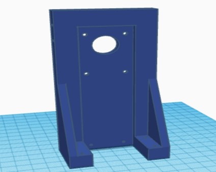
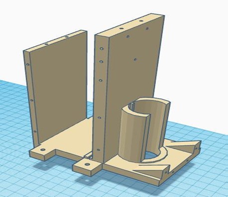
Once the rod-crank-piston mechanism was established, the design of the necessary structural elements to complement the compression system and achieve an integrated functional device was carried out. The designed pieces are detailed in the following table 1.
|
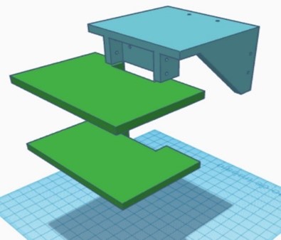
Table 1. Structural elements of the device in the first phase |
|
|
Piston’s guide |
Engine support |
|
|
|
|
Top cover and circuit platforms |
Metal chassis |
|
|
|
To adjust the equipment to the patient, a denim belt with Velcro on one side was made to allow for adjustment.
Hardware – First Phase
In this initial stage, a linear 24VDC power supply was designed and manufactured to power the motor. Additionally, a voltage regulator module was used to provide 5VDC to both the microcontroller and the sensors. To handle all the operations of the equipment, the ESP32 was chosen due to its high processing speed, the ability to execute tasks simultaneously on two cores, and its compact size. To control the motor with the selected microcontroller and supply it with the necessary voltage, an H-bridge module was used.
For measuring the frequency, a magnetic encoder built into the selected gear motor was utilized. Regarding the measurement of compression force, 10KgF pressure sensors were employed. Since the force required to compress a real chest is approximately 40KgF on average, five of these sensors were used. These sensors were connected to the analog channels of the microcontroller using voltage dividers, which allowed for detecting the change in resistance through the voltage change on the analog pin.
Physical assembly– First Phase
In this phase, all the 3D-designed parts were manufactured using PLA, except for the metal chassis, which was constructed with iron. The necessary parts were complemented with bearings, and the structural parts were joined using self-tapping screws. The integration of all the circuitry and power supply into the device was carried out, ensuring an orderly and efficient arrangement of the components. The complete equipment of this initial stage is shown in figure 4.
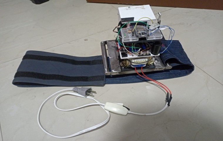
Figure 4. Complete chest compression device from the first phase
Software – First Phase
A simple-natured code was developed for the operation of the device, which is presented in a flowchart in figure 5. This code allows the equipment to start, stop, and adjust the frequency through commands from the graphical user interface (GUI). During the operation of the equipment, force and speed data are continuously sent to the interface for visualization and control.
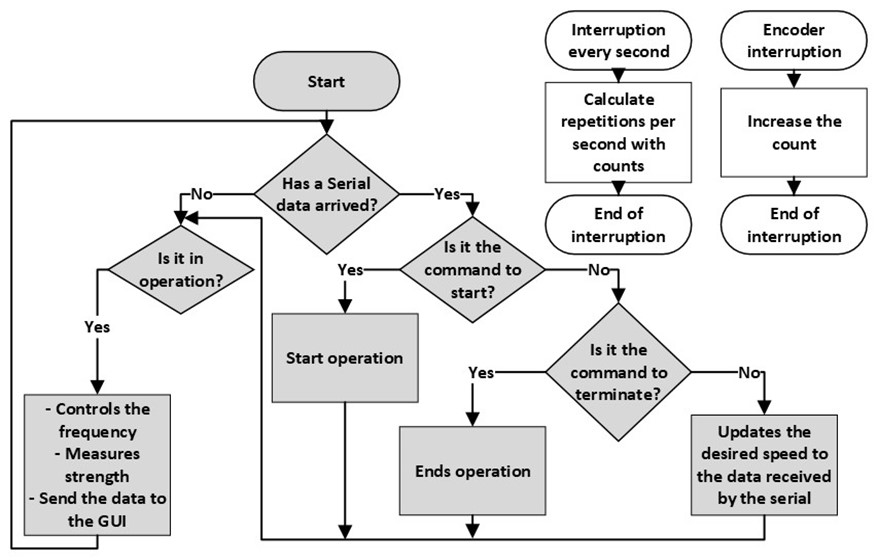
Figure 5. Flowchart of the microcontroller code in the first phase
To measure the operating frequency of the device, a PID control using the motor encoder was implemented. Formula 2 was applied for this purpose. This control was adjusted through trial and error, calibrating the constants Kp, Ki and Kd to ensure optimal performance of the compression system.
![]()
To calculate the force exerted by the FSR sensors, an experimental procedure was carried out by placing different weights on the sensors and recording the readings of the 5 sensors on the analog pins of the ESP32. Subsequently, a piecewise linear approximation method was applied to determine the force exerted from the readings of the analog pins, consolidating formula 3 for this purpose.
![]()
Graphical User Interface (GUI)– First Phase
A desktop application was developed that incorporates a database composed of two main entities: treatments and patients. The treatments entity was related to the patient’s entity through the patient’s unique identifier.
This interface allowed the operation of the equipment by enabling the registration of patients, the search for existing patients, or operation without previous information in case of unknown patient data. Additionally, it allowed control of the equipment’s start, the establishment of the frequency, the visualization of the actual frequency, and the maximum force exerted by the equipment. This ensured the complete recording of treatments along with patient information, providing a comprehensive tool for the management and monitoring of chest compression procedures.
Results and Observations of the Tests – First Phase
An evaluation of the results was carried out based on the requirements established by the American Heart Association (AHA) guidelines for proper Cardiopulmonary Resuscitation (CPR). These results are detailed in table 2.
|
Table 2. Evaluation of the compression device in its first phase fulfilling the requirements established in the AHA guidelines |
|||
|
|
Depth |
Frequency |
Force |
|
Evaluation |
Correct. |
Correct. Adjustable between 50 to 140 repetitions per minute |
Incorrect. Lacks the force to compress a real chest. |
|
Cause |
The compression of the piston is 5cm |
Thanks to the motor’s characteristics |
Limitation due to motor torque |
|
Solution |
- |
- |
Use a motor with more torque. |
Furthermore, the additional features of the equipment were evaluated, as shown in table 3.
|
Table 3. Evaluation of the additional features of the compression device in its first phase |
|||
|
|
Portability |
Interface |
Correct placement control and error management |
|
Evaluation |
Incorrect |
Incorrect |
Incorrect |
|
Cause |
Power supply from the grid and wired communication |
It's not efficient for the equipment to depend on an interface to work |
First, the previous issues must be resolved |
|
Solution |
Use battery and wireless communication |
Implement an independent usage mode for the device |
Once the issues are resolved, placement and error control can be implemented. |
Second Phase
Mechanism and Structure – Second Phase
In this phase, the focus was on providing the equipment with the necessary force to perform compressions on a simulated adult CPR mannequin, certified to withstand a resistance of 40 KgF. Subsequently, it was determined that the motor required to achieve this level of compression should provide a torque of at least 10 Nm. A comprehensive search for powerful motors was conducted, and tests were carried out on the certified CPR mannequin. The results of these tests are presented in table 4, highlighting that the BOSCH F 006 WM0 310 motor met the necessary torque requirement, despite its maximum frequency being limited to 45 rpm, which did not pose a significant obstacle in this phase of the process.
|
Table 4. Selection of a motor with the necessary torque to supply the required compression force |
|||||
|
Motor |
Reducer |
Force without load |
Force of the mechanism |
Speed with manikin |
Observations |
|
21V Drill |
1:78 |
<245rpm |
<40KgF |
0rpm |
Reducer breakage |
|
21V Drill |
Specific to the drill |
>1000rpm |
>50KgF |
>1000rpm |
Hard to control |
|
Car windshield |
Specific to the drill |
<80rpm |
<25KgF |
0rpm |
Motor lacking necessary torque |
|
BOSCH F 006 WM0 310 |
Specific to the drill |
<50rpm |
>45KgF |
<45rpm |
Low frequency |
It is important to note that the PLA-printed crank did not withstand the required force, even during the first test. Therefore, an iron crank was fabricated to carry out the motor tests. Additionally, there was a need to use slightly thicker shafts and bearings to improve the stability of the mechanism.
Taking these observations into account, the crank mechanism was redesigned to use 8x16x5mm bearings and an internal iron reinforcement to prevent breakage during compressions. Likewise, the connecting rod and piston were redesigned to incorporate these bearings and improve the efficiency of the system.
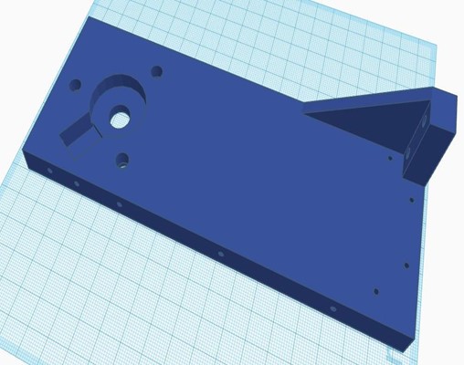
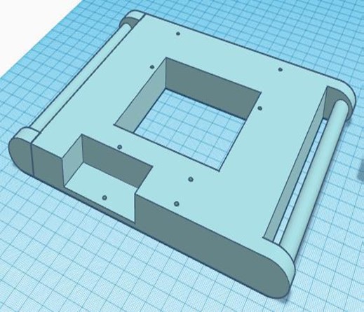
Regarding the structural elements, significant adjustments were made. The platforms for the circuitry were removed, and space was added in the piston guide for the placement of a PCB and a battery. The top cover was adapted to include a removable control panel, while the motor mount and metal chassis were modified to accommodate the new motor. The redesigned parts are shown in table 5.
|
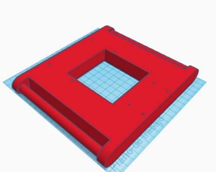
Table 5. Structural elements of the equipment in its second phase |
|
|
Piston rod guide with space for circuitry |
Motor support |
|
|
|
|
Top cover with removable control panel |
Metal chassis |
|
|
|

Hardware – Second Phase
In this stage, improvements were implemented in the hardware of the device to ensure optimal performance and increased portability. A rechargeable 22VDC battery was chosen as the main power source for the motor, while an LM2596 regulator was used to supply 5VDC to the microcontroller and sensors. For the control and management of all equipment operations, the ESP32 microcontroller was retained.
To control the motor and supply high voltage to the motor reducer, a transistor with a current capacity of 5A between the emitter and collector was used in this version. For measuring the frequency, a photoelectric encoder was utilized along with an aluminum disk with 100 slots adapted to the new motor reducer. The same configuration for measuring force from the previous phase was maintained.
Several additional sensors and peripherals were included in this version to improve the portability and usability of the equipment. An OLED screen, buttons, and a rotary encoder were integrated into the control panel. Additionally, an internal real-time clock was added to the device to maintain accurate timekeeping at all times.
Physical Assembly – Second Phase
The new 3D-printed parts were assembled using PLA, along with the reused metal chassis from the previous phase. Bearings were used to ensure smooth movement, and the structural parts were joined with self-tapping screws. The circuitry was implemented on a PCB, and together with the battery, it was integrated into the device. The complete equipment of this second phase is shown in figure 6.
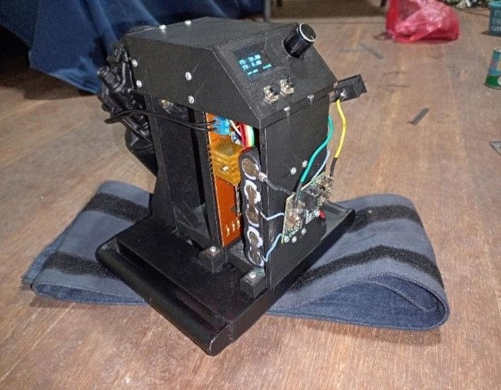
Figure 6. Complete chest compression equipment of the second phase
Software – Second Phase
In this second phase, the code became more complex. The two cores of the ESP32 were utilized, with one assigned for PID control and force measurement, and the other for managing the control panel. Upon startup, the device allows the user to select the desired frequency and then initiate the treatment. Once completed, all relevant data, such as start time, end time, frequency changes, and maximum compression force, are stored in the microprocessor’s EEPROM memory. Subsequently, this data can be transferred via Bluetooth to a graphical user interface for recording along with patient information. The detailed flowchart of this code is presented in figure 7.
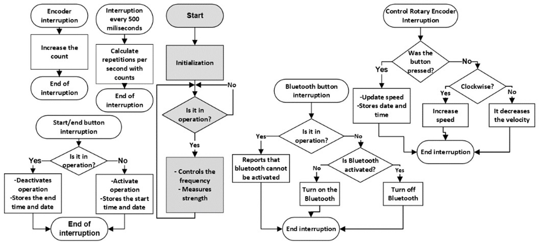
Figure 7. Flowchart of the microcontroller code in the second phase
The algorithms for measuring frequency and force remained similar to those of the first phase, with adjustments in the constants to adapt to the new device model.
Graphical User Interface (GUI) – Second Phase
For this second phase, the desktop application and database used in the previous stage were retained. However, the workflow was modified to accommodate the standalone operation of the equipment and no longer required the presence of the interface to operate. The interface was adjusted to be able to connect via Bluetooth with the device, thus allowing the storage of treatment information carried out with a new patient, as well as with existing patients.
Results and Observations of the Tests – Second Phase
The results were evaluated according to the requirements of the AHA guidelines for proper CPR and are presented in table 6.
|
Table 6. Evaluation of the compression device in its second phase meeting the requirements established by the AHA guidelines |
|||
|
|
Depth |
Frequency |
Force |
|
Evaluation |
Correct |
Incorrect |
Correct. |
|
Cause |
Depth of 5cm |
Limited by motor characteristics |
Thanks to the selected motor |
|
Solution |
- |
Using a motor with higher speed |
- |
The additional features of the device were also evaluated, as shown in table 7.
|
Table 7. Evaluation of the additional features of the chest compression device in its second phase |
|||
|
|
Portability |
Interface |
Correct placement control and error management |
|
Evaluation |
Correct |
Correct |
Incorrect |
|
Cause |
No connection to the grid or wired communication |
Stores treatments in the interface |
First, the previous issues must be resolved |
|
Solution |
- |
- |
Once the issues are resolved, placement and error control can be implemented |
It is important to note that during the long-duration tests, a high level of frictional force between the piston and its lateral guide was identified. It was deemed necessary to lengthen the connecting rod in the third phase of the project to address this issue.
Third Phase
Mechanism and Structure – Third Phase
The third phase of development focused on achieving the appropriate levels of frequency, depth, and force necessary for effective chest compression during cardiopulmonary resuscitation. To achieve this, a motor with a torque greater than 10 Nm and a frequency higher than 120 rpm was sought. After analysis, the D63L-2445-180R motor, which met these specifications, was selected.
All mechanism parts were adapted to the new motor, taking into account observations made in previous phases, such as the need to lengthen the connecting rod. In this stage, it was decided to keep the crankshaft and plunger unchanged, while research was conducted to determine the appropriate length of the connecting rod. It was found that in the design of a crank-connecting rod mechanism, it was recommended for the connecting rod to have a length four times greater than the crankshaft.(17) As a result, a connecting rod with a length of 10 cm was designed, keeping the other characteristics of the original design intact.
Adjusting the length of the connecting rod involved additional modifications to the plunger guide and motor support, ensuring that the connecting rod could fit properly. Additionally, side covers were introduced to cover the mechanism and circuitry, providing an aesthetic and safe appearance to the device.
Hardware – Third Phase
In this phase, the use of a rechargeable 22VDC battery to power the motor was maintained. However, to regulate the voltage to 5VDC for the sensors and microcontroller, an LM7805 voltage regulator was implemented. The ESP32 remained the chosen microcontroller. For motor control by the microcontroller and supplying high voltage to the motor reducer, a transistor with a current capacity of 10A between the emitter and collector was used in this version. The use of the photoelectric encoder to measure frequency, along with an aluminum disc with 100 slots adapted to the new motor reducer, was retained. Regarding force measurement, the configuration used in previous phases was retained. In addition to the peripherals used in the previous phase, two additional components were added: one for measuring current in the motor and another for measuring voltage in the battery.
Physical Assembly – Third Phase
All the modified parts were 3D printed using PLA, while the existing parts that did not require modifications were retained. The new circuitry was implemented on a printed circuit board (PCB), which was integrated into the device along with the battery. The complete equipment from this third phase is depicted in figure 8.
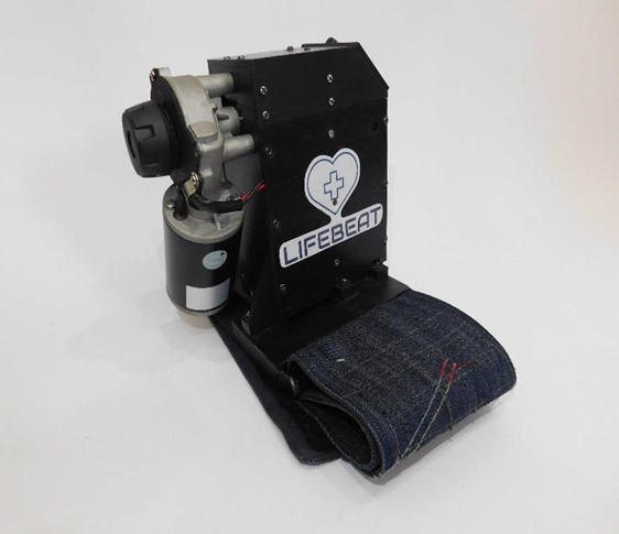
Figure 8. Chest compression device complete in its third phase
Software – Third Phase
In this third phase, the code was improved to add key functionalities and enhance safety. Wi-Fi communication was implemented, along with operating modes to adapt to different scenarios. Algorithms were added to verify proper device placement, ensuring patient safety. Battery status was included in the OLED display. A software module for remote maintenance of the device via the Wi-Fi interface was developed, allowing for device management. The detailed flowchart is available in figure 9.
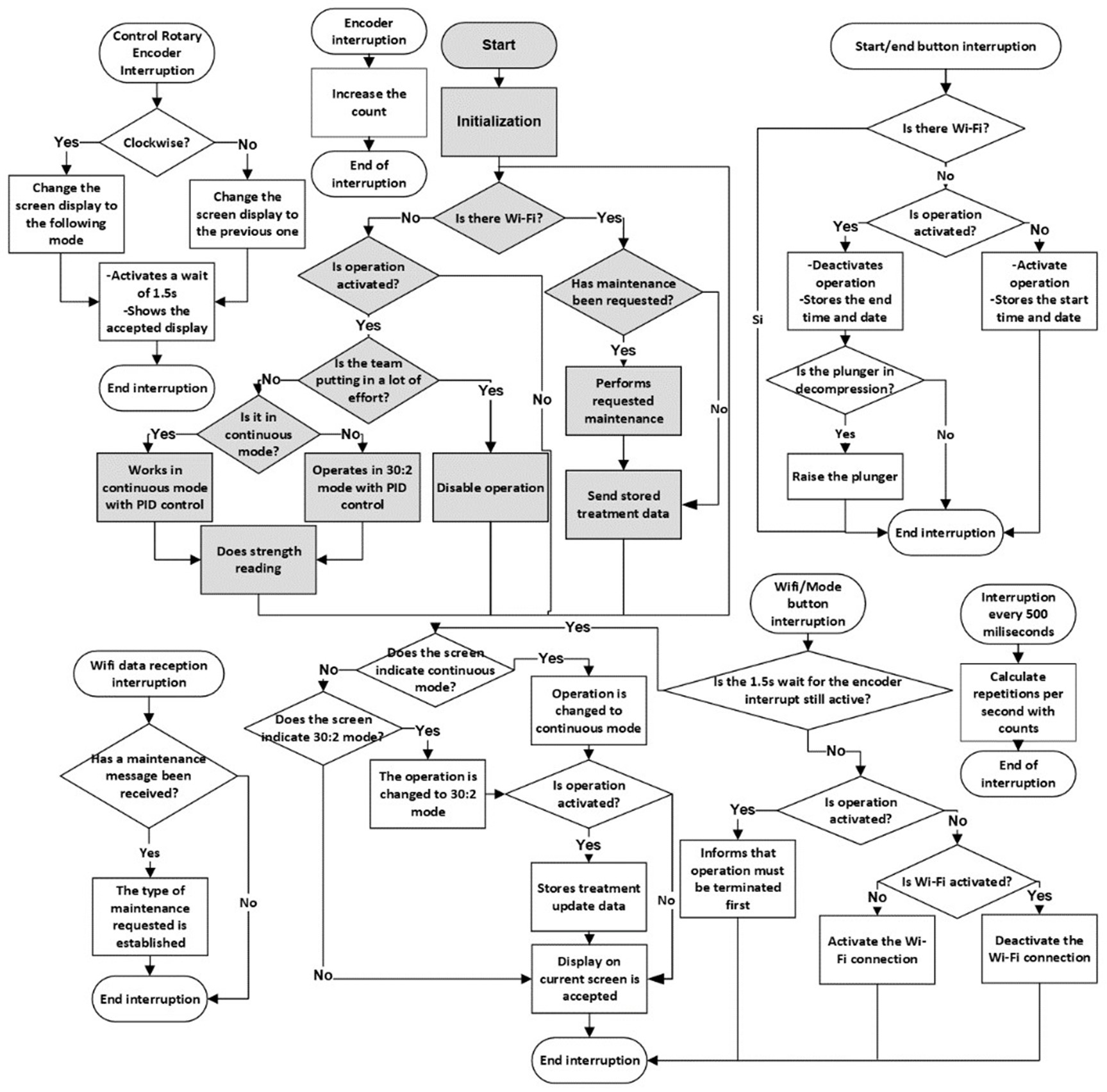
Figure 9. Flowchart of the microcontroller code in the third phase
Graphical User Interface (GUI) – Third Phase
For this phase, a web application was developed with access levels, each with specific functions, as detailed in the use case diagram in figure 10.

Figure 10. Use Case Diagram of the Web Application
The user interface provides users with the ability to register new patients and manage treatments, while administrators have the capability to manage users. A notable feature in this version is the service level, which facilitates equipment maintenance through a dedicated window in the web application, as depicted in figure 11. This ensures that the equipment remains in optimal working condition at all times.
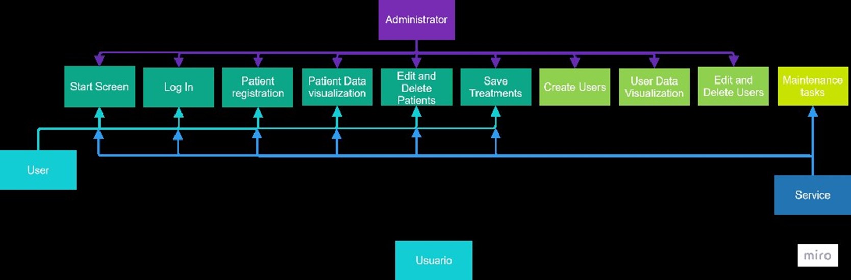
Figure 11. Maintenance Window of the Web Application
Results and Test Observations – Third Phase
The results of the device in the third phase are summarized in table 8 below.
|
Table 8. Evaluation of the compression device in its third phase |
|
|
Variable |
Result |
|
Depth |
5 cm |
|
Frequency |
120rpm [±5rpm] |
|
Force |
54 KgF |
|
Portability |
Completely portable. Battery autonomy of 20 minutes with charge visualization on the OLED screen. |
|
Interface |
Web application for recording treatments with respective patients, featuring a special interface for service. |
|
Error management |
- Detection of proper placement - Detection of motor overload |
The results demonstrated that the compression device satisfactorily met the requirements established by the AHA regulations and maintained optimal performance in all its additional features.
DISCUSSION
The results obtained with the prototype chest compression device using the crank-slider-piston system are consistent with those of another study conducted by Alam et al. 2018. In their study, they developed a compressor that operates at 103-105 repetitions per minute with a depth of 5,13 centimeters.(18) In contrast, the device developed in this research achieves a frequency of 120 rpm ± 5 and an exact depth of 5 centimeters. Both designs meet the criteria established by the AHA guidelines, which require between 100 and 120 repetitions per minute and a depth greater than 5 centimeters. The difference in results between the models is primarily due to two factors: the selection of the motor, which defines the device’s frequency and force, and the length of the crank, which determines the compression depth. Another study takes advantage of this characteristic of the crank to develop a compression device with adjustable depth for patients of different ages.(19) In contrast, the prototype developed in this research is limited to adults.
This prototype proposes a new way of implementing chest compression devices using 3D printing, unlike the mentioned studies that use metals for their prototypes. This allows the device to be smaller and lighter, thus increasing its portability. No information has been found on other studies using this technology, suggesting that it could be a new way to facilitate the manufacturing of these devices and enhance their portability.
The prototype provides a solution to the issue of difficult acquisition of these devices in Bolivia and developing countries, as the total cost of the device materials does not exceed 350 US dollars. Thanks to 3D printing, its manufacturing is easy with local technology, compared to commercial devices such as the LUCAS 3.1, which costs 20 015 dollars,(20) or the AutoPulse, which reaches 19 950 dollars.(21)
Functionally, the device offers two modes of use: the first is the 30:2 mode, established by AHA guidelines,(10) where the device performs 30 compressions and then pauses for a set time to allow for two ventilations. The second mode, called “continuous,” performs compressions at 120 repetitions per minute without pauses until the treatment ends. This mode is useful in cases of suspected COVID-19, where mouth-to-mouth resuscitation is not recommended, or during patient transport.
The developed prototype has two unique features not found in other similar studies or commercial devices. The first is the inclusion of force sensors that detect the proper placement of the prototype, ensuring correct operation. This feature could be implemented in commercial devices to enhance the safety of correct CPR, as it alerts if the contact with the patient is not adequate, allowing for adjustment of the device. The second feature is the device’s ability to connect to a web application, facilitating patient information storage and the creation of procedure records, integrating with emerging technologies such as Hospital Information Systems (HIS). This proposal would allow cardiopulmonary resuscitation equipment to store relevant patient information in an integrated system, improving patient care and maintaining a CPR history.
CONCLUSIONS
This prototype demonstrates the technological capabilities of our researchers, specifically in the area of cardiopulmonary resuscitation, which has been standardized globally for many years. The availability of a device with these characteristics could revolutionize the management of chest compressions in our region, emphasizing practical utility, local availability, and economic accessibility. Furthermore, the use of 3D printing technology allows for rapid prototyping and customization, enabling continuous improvements and adaptations to meet specific needs and constraints. It is crucial to conduct further validations using additional mannequins and, eventually, in real-life scenarios. These future tests will not only verify the device’s efficacy but also help refine its design and functionality to ensure it meets the highest standards of performance and reliability in emergency situations. The integration of this device into existing healthcare systems could significantly enhance the quality of care provided during cardiac emergencies.
BIBLIOGRAPHIC REFERENCES
1. Cordero-Escobar, I., De Dios Soler-Morejón, C.: Principios éticos de la reanimación cardiopulmonar y cerebral. Revista Mexicana de Anestesiología. 43, 5-7 (2020). https://doi.org/10.35366/cma201a
2. What is CPR. In: cpr.heart.org. https://cpr.heart.org/en/resources/what-is-cpr
3. Kleinman, M.E., Brennan, E., Goldberger, Z.D., Swor, R.A., Terry, M.A., Bobrow, B.J., Gazmuri, R.J., Travers, A.H., Rea, T.D.: Part 5: Adult Basic Life Support and Cardiopulmonary Resuscitation Quality. Circulation. 132, (2015). https://doi.org/10.1161/cir.0000000000000259
4. Gu W, Li C-S (2017b) Ventilation strategies during out-of-hospital cardiac arrest: a problem that should not be neglected. Journal of Emergency and Critical Care Medicine 1(9):23. https://doi.org/10.21037/jeccm.2017.08.08
5. Aygün, M., Yaman, H.E., Genç, A., Karadağlı, F., Eren, N.B.: Mechanical Chest Compression Devices: Historical Evolution, Classification and Current Practices, A Short Review. Eurasian Journal Of Emergency Medicine. 15, 94-104 (2016). https://doi.org/10.5152/eajem.2016.74936
6. Ochoa, F.J., Ramalle-Gómara, E., Lisa, V., Saralegui, I.: The effect of rescuer fatigue on the quality of chest compressions. Resuscitation. 37, 149-152 (1998). https://doi.org/10.1016/s0300-9572(98)00057-4
7. (2021) BLS Algorithms 2023 (Basic Life Support). In: United Medical Education. https://www.acls-pals-bls.com/algorithms/bls/
8. Stiell, I.G., Brown, S.P., Christenson, J.M., Cheskes, S., Nichol, G., Powell, J., Bigham, B.L., Morrison, L.J., Larsen, J., Hess, E.P., Vaillancourt, C., Davis, D.P., Callaway, C.W.: What is the role of chest compression depth during out-of-hospital cardiac arrest resuscitation?*. Critical Care Medicine. 40, 1192-1198 (2012). https://doi.org/10.1097/ccm.0b013e31823bc8bb
9. Mayanz, S.: El riesgo versus beneficio del LUCAS (dispositivo mecánico de compresiones torácicas). De revista Anesthesiology. - Reanimación, https://reanimacion.net/2014/06/25/el-riesgo-versus-beneficio-del-lucas-dispositivo-mecanico-de-compresiones-toracicas-de-revista-anesthesiology/, (2014)
10. Panchal AR, Bartos JA, Cabañas JG, Donnino MW, Drennan IR, Hirsch KG, Kudenchuk PJ, Kurz MC, Lavonas EJ, Morley PT, O’Neil BJ, Peberdy MA, Rittenberger JC, Rodriguez AJ, Sawyer KN, Berg KM, Arafeh J, Benoit JL, Chase M, Fernandez A, De Paiva EF, Fischberg BL, Flores GE, Fromm P, Gazmuri R, Gibson BC, Hoadley T, Hsu CH, Issa M, Kessler A, Link MS, Magid DJ, Marrill K, Nicholson T, Ornato JP, Pacheco G, Parr M, Pawar R, Jaxton J, Perman SM, Pribble J, Robinett D, Rolston D, Sasson C, Satyapriya SV, Sharkey T, Soar J, Torman D, Von Schweinitz B, Uzendu A, Zelop CM, Magid DJ (2020) Part 3: Adult Basic and Advanced Life Support: 2020 American Heart Association Guidelines for Cardiopulmonary Resuscitation and Emergency Cardiovascular Care. Circulation 142(16_suppl_2). https://doi.org/10.1161/cir.0000000000000916
11. Arribas, L.S.: Compresiones torácicas mecánicas versus manuales en adultos en parada cardiorrespiratoria extrahospitalaria durante su traslado en ambulancia: una revisión sistemática. NURE Investigación. (2023). https://doi.org/10.58722/nure.v20i122.2237
12. Steen, S., Sjöberg, T., Olsson, P.-I., Young, M.P.: Treatment of out-of-hospital cardiac arrest with LUCAS, a new device for automatic mechanical compression and active decompression resuscitation. Resuscitation. 67, 25-30 (2005). https://doi.org/10.1016/j.resuscitation.2005.05.013
13. Czyż, R., Leśkiewicz, M., Czyż, I.: Mechanical devices to compress the patient’s chest in a state of sudden cardiac arrest - future or everyday life of emergency medicine. Journal of Education, Health and Sport. 1, 51- 66 (2018). http://dx.doi.org/10.5281/zenodo.1185318
14. Aygün, M., Yaman, H.E., Genç, A., Karadağlı, F., Eren, N.B.: Mechanical Chest Compression Devices: Historical Evolution, Classification and Current Practices, A Short Review. Eurasian Journal Of Emergency Medicine. 15, 94-104 (2016). https://doi.org/10.5152/eajem.2016.74936
15. Manual de usuario Weil Mini (15 páginas), https://www.manual.do/weil/mini/manual
16. Biela – Manivela – émbolo, https://harnalmanchola.wordpress.com/2013/08/18/biela-manivela-embolo/
17. Cejarosu: Mecanismo biela-manivela, https://www.iesmarenostrum.com/departamentos/tecnologia/mecaneso/mecanica_basica/mecanismos/mec_biela-manivela.htm
18. Alam MdM, Hussain M, Amin MdA, Khan MM (2018) Design of a Low-cost Automated Cardiopulmonary Resuscitation Device with Piston-Driven Chest Compression System. IEEE. https://doi.org/10.1109/ceeict.2018.8628060
19. Sung C-W, Wang H-C, Shieh J-S, Jaw F-S (2020) A novel mechanical chest compressor with rapid deployment in all population cardiopulmonary resuscitation. Scientific Reports 10(1). https://doi.org/10.1038/s41598-020-63058-9
20. LUCAS® 3.1 Chest Compression System | AED Superstore - 99576-000063. In: AED Superstore. https://www.aedsuperstore.com/physio-control-99576-000043-lucas-3-chest-compression-system.html
21. Defib Shop (2024) ZOLL AutoPulse® (8700-0730-01) - Defibshop. In: Defibshop. https://www.defibshop.com.au/product/zoll-autopulse/
FINANCING
The authors did not receive financing for the development of this research.
CONFLICT OF INTEREST
The authors declare that there is no conflict of interest.
AUTHORSHIP CONTRIBUTION
Investigation: Marco Fabian Borda Wiegert, Mauricio Marcelo Peredo Claros, Eynar Calle Viles, Rommer Alex Ortega Martinez.
Methodology: Marco Fabian Borda Wiegert, Mauricio Marcelo Peredo Claros, Eynar Calle Viles, Rommer Alex Ortega Martinez.
Drafting - original draft: Marco Fabian Borda Wiegert, Mauricio Marcelo Peredo Claros, Eynar Calle Viles, Rommer Alex Ortega Martinez.
Writing - proofreading and editing: Marco Fabian Borda Wiegert, Mauricio Marcelo Peredo Claros, Eynar Calle Viles, Rommer Alex Ortega Martinez.